We supply customized oval flange Neodymium magnets.
Stadium-shaped profile with a large central bore.
And two mounting holes positioned on opposite lobes.
This geometry combines magnetic function with mechanical mounting:
– The magnet itself serves as the flange, bolted directly to your assembly (no separate housing required).
– And the central bore provides clearance for a shaft, sensor body, or cable bundle.
Common in motor mounting, actuator brackets, sensor housings, and fixtures.
Such applications require bolt-down mounting and central clearance.
Manufactured using diamond drilling for the central bore and wire EDM for the outer profile and mounting holes.
Mounting hole position tolerance typically ±0.1 mm to ensure alignment with tapped holes in your assembly.
The Engineering Logic: A “3-in-1” Solution
Why is this shape better than a standard ring?
1. Mechanical Fastening (No Glue Needed):
The Problem:
– Gluing a standard ring magnet is messy and unreliable in high-heat or vibrating machinery.
The Solution:
– The two small side holes allow you to use M1.6, M2, or M3 screws to mechanically fasten the magnet.
– This guarantees zero slippage over the product’s life.
2. Space Efficiency (The Oval Shape):
The Problem:
– A round flange might be too wide for your housing.
The Solution:
– By using a “Stadium” (Oval) profile, we shave off the sides.
– They can fit a powerful magnet into a narrow, elongated space.
– Meanwhile, keep the functionality of a ring.
3. Pass-Through Utility:
The Function:
– The large center hole isn’t for mounting; it’s a clearance hole.
The Application:
– It allows a rotating shaft, an optical lens.
– Or, a wire harness to pass through the center of the magnetic field.
Critical Manufacturing Note: Wall Thickness
Fragility Warning:
Look at the “web” (the thin strip of material) between the large center hole and the outer edge.
The Limit:
– If this wall thickness is less than 1.5mm, the magnet becomes extremely fragile.
– It may crack when you tighten the screws in the side holes.
Our Recommendation:
– Please design your part with sufficient wall thickness to handle the torque of the mounting screws.
Manufacturing Method
Machining:
– This shape cannot be pressed.
– We typically slice the oval blank and then use CNC Diamond Drilling for the holes.
Chamfering:
– We apply chamfers to all three holes and the outer rim.
– This is vital to prevent the plating from building up on the sharp edges of the holes.
– Otherwise, the plating would otherwise tighten the clearance.
Surface Coatings
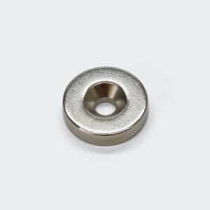
Nickel (Ni-Cu-Ni):
– As shown.
– Provides a hard, durable surface.
Zinc (Zn):
– A good option if the magnet is hidden inside a machine.
Parylene:
– Recommended if the screws might scratch the plating.
– Parylene resists chipping better than Nickel.
Applications
Optical Sensors: The magnet mounts around a camera lens (via the center hole) to attach magnetic filters or covers.
Robotics: A flange magnet on a robotic wrist that allows cables to pass through the middle.
Door Latches: The oval shape fits on the narrow edge of a door frame, screwed in for security.
Hall Effect Arrays: The center hole fits over a rotating shaft, while the magnet triggers stationary sensors.
Ordering Guide: The “Hole Map”
To quote this complex part, we need a detailed drawing or the following data:
1). Outer Dimensions: Length x Width x Thickness.
2). Center Hole: Diameter (IDlarge).
3). Mounting Holes: Diameter (IDsmall) and Hole Type (Straight or Countersunk?).
4). Hole Pitch: The exact distance between the centers of the two small holes (C-to-C).
5). Magnetization: Through Thickness?