
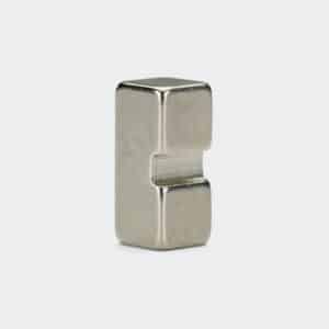
We supply custom Neodymium block magnets with machined notches, channels, grooves.
Or slots cut into the magnet body.
These cutouts serve two main purposes:
– Mechanical locking – the notch acts as a keyway to prevent the magnet from sliding or rotating
– Clearance – creates space for wires, screw heads, guide rails, or other components to pass through
– We can combine slot machining with additional features like radiused (rounded) edges for safer handling and improved durability in assembly.
Specify your block dimensions, notch location, depth and width, and any edge treatments required.
The Engineering Logic: Why Cut a Notch?
1. Anti-Rotation & Locking (Keying):
In high-vibration environments (like motors or heavy machinery), glue alone might fail.
The Function:
– The notch mates with a corresponding “rib” or “key” in your housing.
The Benefit:
– This mechanically locks the magnet in position.
– Prevent it from sliding laterally or rotating, even under extreme torque.
2. Wire & Component Clearance:
The Function: The slot provides a safe “tunnel.”
The Benefit:
– Allows you to route wires, fit a thermocouple.
– Or clear a screw head underneath the magnet without lifting the magnet off the mounting surface.
Technical Geometry: Defining the “Cut”
Please provide specific dimensions to quote this.
Standard L x W x H isn’t enough.
To manufacture this part, we control the notch geometry with precision grinding:
– Slot Width (Ws): The width of the channel.
– Slot Depth (Ds): How deep is the cut? (e.g., 2mm deep).
Position:
– Is the slot perfectly Centered (symmetrical)?
– Or Offset to one side?
Profile:
– Is the bottom of the slot flat (rectangular)?
– Or curved (radius)?
Expert Note: The “Rounded” Finish
Durability Upgrade:
The magnet in the photo features Heavy Radius Corners rather than sharp edges.
Why do this?
If you are using the notch for “Mechanical Locking,” the magnet will experience stress/shear force at the edges.
Sharp corners would snap off.
Our Recommendation:
For notched magnets, we strongly suggest adding a 1mm – 2mm Radius to all outer edges.
Maximize their structural strength and impact resistance.
Magnetization Orientation
The presence of a notch affects the magnetic flux path.
Through Thickness (Standard):
– Magnetized through the notched face.
– The notch simply creates a small air gap in the field.
Through Length:
– The poles are on the ends.
– The notch does not interfere with the pole faces.
Surface Coatings
Plating a magnet with a deep slot requires care to avoid “shielding”.
It’s where plating doesn’t reach the bottom of the groove.
Nickel (Ni-Cu-Ni):
– As shown.
– Our process ensures fully uniform coverage inside the slot to prevent corrosion at the bottom of the cut.
Epoxy:
– Recommended if the slot is used for wire routing.
– Provide electrical insulation.
Parylene:
– For micro-slots with very tight tolerances.
Applications
Linear Motors: Magnets locked onto a track using the notch as a guide rail.
Cable Management: Holding cables against a steel surface while allowing one specific cable to run under the magnet.
Sensor Mounts: The notch fits over a PCB component.
Safety Interlocks: The shape acts as a physical “key”—the machine only turns on if the magnet with the correct notch profile is inserted.
Ordering Guide: Critical Data
To quote this, we need a sketch or the following 5 dimensions:
1). Block Size: Length x Width x Thickness.
2). Notch Width: (Ws)
3). Notch Depth: (Ds)
4). Notch Position: (e.g., “Centered on the 20mm face”).
5). Edge Style: “Standard Sharp” or “Rounded/Radiused” (as shown)?