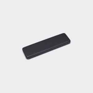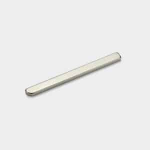
We supply customized Neodymium bar magnets with chamfered or radiused ends.
One or both ends machined with beveled edges or rounded corners instead of sharp 90° edges.
The chamfer or radius (typically 0.5–2 mm) eases insertion into tight slots, channels, or recesses.
Allow the magnet to guide itself into position rather than catching on sharp edges.
This reduces installation force and minimizes risk of corner chipping during assembly.
Particularly, in automated or high-speed production lines.
Common in battery compartments, sliding drawer assemblies, sensor housings.
And any application requiring repeated insertion/removal or blind assembly.
The Engineering Logic: Why the “One-End” Chamfer?
1. Automated Insertion (The “Lead-In”):
If you are pressing magnets into a slot using automated machinery:
The Problem:
– Sharp-cornered magnets require perfect alignment.
– If they are off by even 0.1mm, they catch on the lip of the housing and jam the machine.
The Solution:
– The chamfered end acts as a Guide.
– It funnels the magnet into the slot, correcting minor misalignments automatically.
2. Poka-Yoke (Orientation Keying):
The Function:
– By chamfering only one end (making the magnet asymmetric), you create a physical or visual indicator.
The Benefit:
– Assembly workers instantly know which end is “front” or which polarity is “up”.
– Prevent reverse installation errors (Poka-Yoke).
3. Mating with Milled Pockets:
The Function:
– CNC-milled slots often have rounded corners at the bottom.
The Benefit:
– A magnet with a matching radiused end fits flush to the bottom of the pocket.
– Usually, a square magnet would hit the radius and sit too high there.
Geometric Definitions
To manufacture this, we need to distinguish between the two ends.
We customize the profile to your specific assembly needs:
– End A (The Lead-In): Heavily chamfered or Radiused (e.g., R2.0mm).
– End B (The Stop): Standard sharp corners (or light edge break).
– Cross Section: Width x Thickness.
– Length: Total overall length.
Magnetization Orientation
For long bars, this is the most critical question.
Through Thickness:
– The large flat faces are North/South.
– Common for holding bars.
Through Width (Lateral):
– Common for motor slots.
Through Length (Axial):
– Common for reed switch activation.
Handling Warning: Beam Strength
Long, thin magnets are structurally weak.
Fragility Note:
A long, thin Neodymium bar (e.g., 50mm long, 2mm thick) has very low “Beam Strength.”
Risk:
– It will snap easily if bent or if it slams flat against a steel surface.
Handling:
– Must be handled with care during installation.
– We recommend sliding them into place, not snapping them down.
Surface Coatings
Nickel (Ni-Cu-Ni):
– As shown.
– The smooth, polished nickel helps the magnet slide into tight slots with low friction.
Epoxy:
– Recommended if the magnet is being glued into a carbon fiber or aluminum slot (better adhesion).
Parylene:
– For battery electrolytes or corrosive environments.
Applications
EV Battery Packs: Long bars inserted between cells for structural or sensing purposes.
Knife Holders: The internal magnet bars inside a wood block.
Linear Sensors: Position detection along a track.
Security Switches: Window/Door alarm sensors where the magnet slides into a narrow plastic housing.
Ordering Guide: Specifying the Ends
To quote this accurate, please use the following format:
1). Dimensions: Length x Width x Thickness.
End Style:
2). Symmetric: Both ends chamfered?
3). Asymmetric: “One end Radius, One end Square” (as shown)?
4). Magnetization: Thickness, Width, or Length?
5). Application: “Is this being pressed into a slot?” (We can adjust tolerances for a slide-fit).