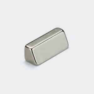
We supply Neodymium magnets with a trapezoidal profile.
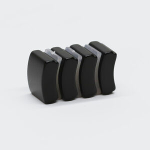
A wide base tapering to a narrower top face, with radiused (rounded) edges instead of sharp corners.
This geometry is designed for rotor assemblies in electric motors and generators.
The tapered sides allow the magnet to be mechanically locked into dovetail-shaped rotor slots.
Prevent movement during rotation.
The radiused edges reduce stress concentrations and improve mechanical durability in high-speed applications.
Common in permanent magnet motors, servo motors.
And generator rotors where secure magnet retention is critical.
Specify your taper angle, base width, top width, thickness, and edge radius requirements.
The Engineering Logic: “Dovetail” Retention
1. Mechanical Locking (The Wedge Effect):
In high-speed motors, centrifugal force tries to throw the magnets off the rotor.
Glue alone is often not enough.
The Solution:
– The tapered sides of this magnet act as a Dovetail Wedge.
– When inserted into a matching slot, the geometry physically prevents the magnet from flying out, regardless of glue failure.
2. Stress Reduction (The Rounded Edges):
The Detail: The magnet in the photo has soft, rounded corners.
The Reason:
– If you insert a sharp-cornered magnet into a steel rotor slot, the sharp point creates a “Stress Riser” in the steel.
– This can cause the rotor to crack at high speeds.
– Our Radiused Edges distribute the stress evenly.
– They protect both the magnet and your rotor lamination stack.
Geometric Definitions: Defining the Taper
Trapezoids are hard to measure.
To manufacture this part accurately, we control the following cross-sectional dimensions:
– Bottom Width (Wmajor): The widest part of the base.
– Top Width (Wminor): The narrowest part of the top.
– Height (H): The thickness.
– Taper Angle: The angle of the side walls (usually symmetrical).
– Edge Radius (R): The curvature of the corners (as seen in the photo).
Magnetization Orientation
Parallel (Through Thickness):
– The North/South poles are on the Top and Bottom flat faces.
– Standard for surface-mounted or buried motor magnets.
Lateral (Through Width):
– Magnetized side-to-side.
Surface Coatings
Ni-Cu-Ni (Nickel):
– As shown in the photo.
– The rounded edges allow for a very thick, high-quality plating layer that is resistant to corrosion.
Phosphated:
– Recommended if the magnet will be embedded/buried inside a rotor slot (better epoxy adhesion).
Epoxy:
– For outdoor or exposed applications.
Applications
Interior Permanent Magnet (IPM) Motors: Magnets buried inside the rotor steel.
High-Speed Spindles: Where mechanical retention is mandatory.
Magnetic Couplings: Wedge-shaped magnets that lock into a hub.
Halbach Arrays: The tapered shape allows for flux focusing in circular arrays.
Ordering Guide: What We Need
To quote this item, “Length x Width x Height” is insufficient.
We need a drawing or the following:
1). Dimensions: Bottom Width, Top Width, Height, Length.
2). Edge Condition: “Sharp Corners” or “Radiused/Rounded” (as shown)? This is critical.
3). Application Temp: Does the motor run hotter than 80°C? (We will suggest SH/UH grades).
4). Magnetization Direction: Through the height or the width?